Ported Vacuum Manifold Cover
Purpose
The purpose of this change is to eliminate the beating noise that is produced by some vacuum pump modules.
|
|
Caution—Read the entire procedure before beginning. This procedure involves opening the Panthers Waste Manifold and requires careful handling to avoid contamination of the system. |
Parts and Materials Required
- Absorbent Pad
- 50/50 Bleach
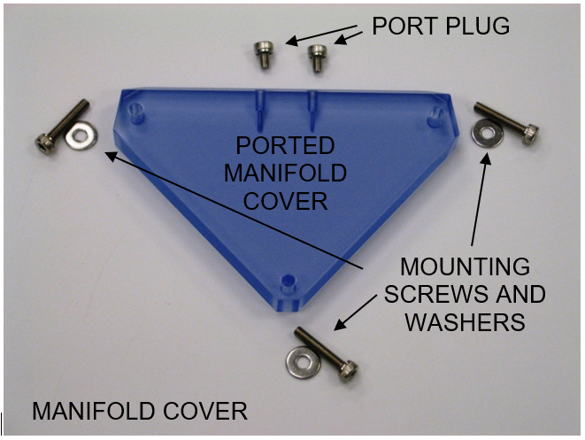
- Kit, Manifold Cover
- Ported Vacuum Manifold Cover
- 3x M3x16 Mounting Screws
- 3x M3 Flat Washers
- 2x M3x4 Plug Screws
- 2.5 mm Hex Key
- Vacuum Filter - If Required, see procedure.
Time Required
- 45 minutes
Procedure
Preparation
- Put on proper PPE.
- Verify that the vacuum system is performing properly by checking the vacuum level by either using the "Temperatures and Sensors" screen in the Panther User Interface or the Service Software method described in the Configuration section below. The vacuum level should be between 6 and 8 in Hg (-203 and -271 mbar).
- Address any problems (leaks, clogged filter, etc.) that result in low vacuum levels prior to proceeding with the installation of the ported vacuum manifold cover.
- Power down the Panther System.
- Replace the vacuum filter in the waste drawer if it has been more than 3 months since a new filter was installed.
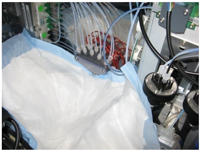
- Open the right-side door panel and locate the vacuum manifold.
 Place an absorbent pad under the vacuum manifold to catch any dropped components and to absorb any fluid leaks.
Removal
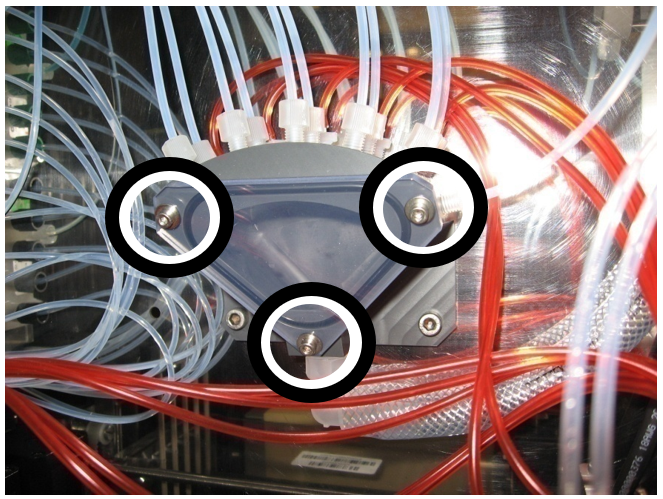
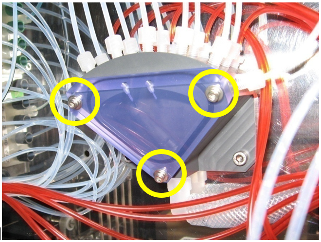
- Remove the original (non-ported) vacuum manifold cover by removing the 3 M3 mounting screws and washers using a 2.5 mm hex key.
- Decontaminate the original manifold cover, mounting screws, and washers immediately after removal with 50/50.

Caution—DO NOT place the cover where it may contaminate surrounding areas prior to decontamination. - Discard the original manifold cover, mounting screws, and washers according to current laboratory practices.
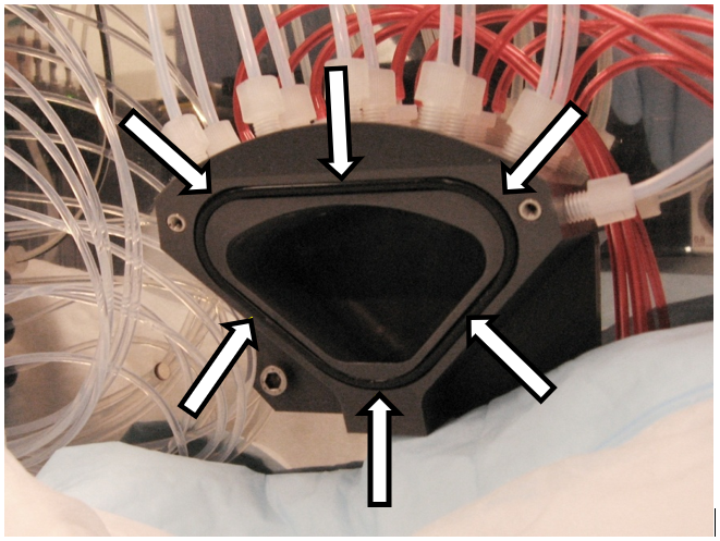
- Visually inspect that the O-Ring seal remains in the seal gland (groove).

Note—Make sure the seal is properly seated in the gland before installing the new cover. Vacuum grease can be used as needed in the seal gland to aid in seal fitting and retention.
Installation
- Check that all parts are included in the manifold cover kit.
- Make sure the O-Ring seal is properly seated in the seal gland (groove).
- Place the new ported vacuum manifold cover onto the front of the vacuum manifold and secure it with the 3 M3x16 screws and the 3 M3 washers.
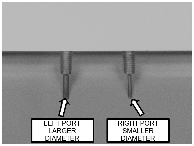
Note—Do not over tighten the mounting screws. - There are two ports in the ported manifold cover.
Before powering on the system, ensure both port plugs are removed (plug screws are not installed).
Retain the port plug screws for use in the configuring the ports as described below. - Power on the Panther System.
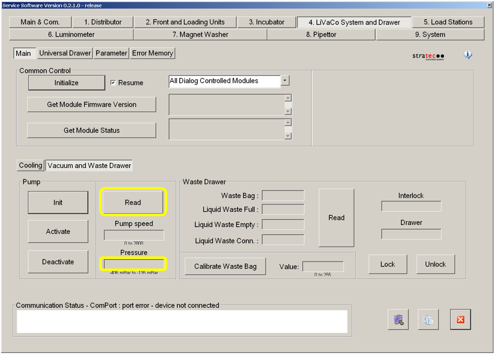
- Start the Service Software.
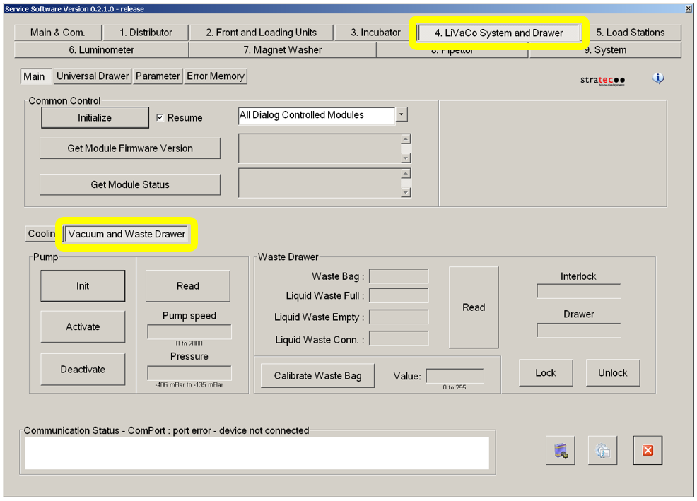
- Select the "4. LiVaCo System and Drawer" tab and select "Vacuum and Waste Drawer" button in the lower section.
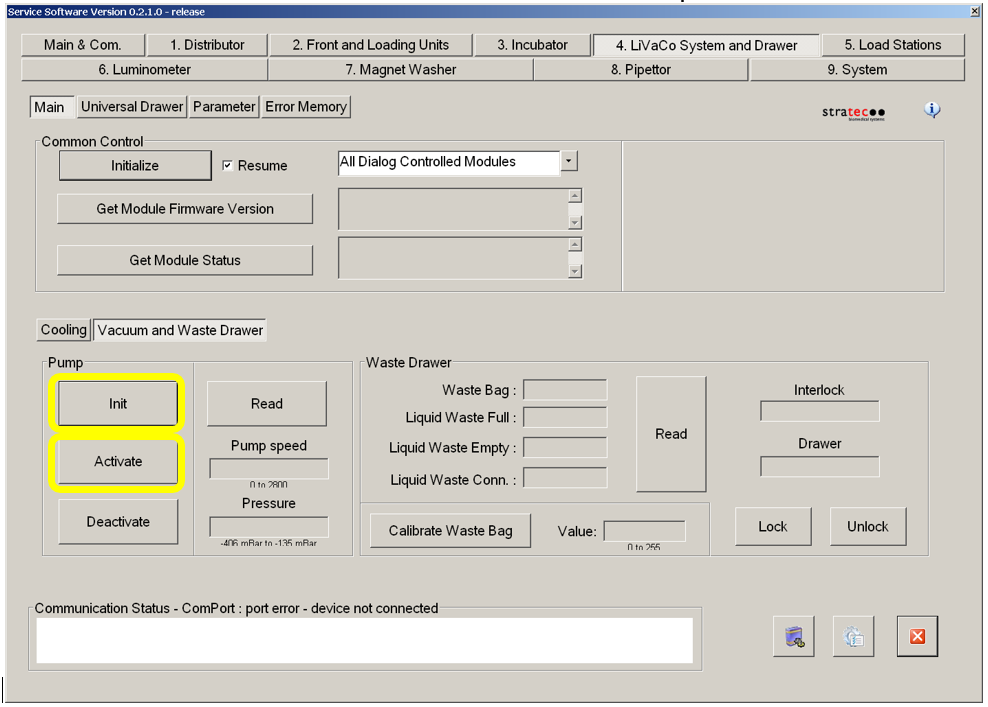
- Select "Init" button then the "Activate" button in the "Pump" section.
- Allow the vacuum system to run for at least 5 minutes.
Configuration
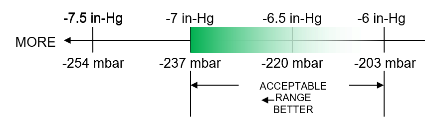
The optimum vacuum is between -203mbar and -270mbar and the vacuum pump speed must read above 1650rpm
- Verify the first manifold cover configuration by reading the vacuum level using Service Software.
- Configure the manifold cover for each of the other configurations as necessary by installing the M3x4 port plug screws using a 2.5mm Allen key (do not over tighten the plug screws).
Evaluate the vacuum level of each configuration by reading the vacuum level using Service Software. - Select the appropriate configuration.
The manifold ports must be configured to achieve the optimum vacuum level.
Panther Systems that are installed at sites located in higher elevations may require different configurations than systems at lower altitudes.
There also may be variability in system performance from one system to another.
The configurability of the ports allows the system to be set up to accommodate these variations.
The optimum vacuum is between -203mbar and -270mbar and the vacuum pump speed must read above 1650rpm
Vacuum levels above 237 mbar will cause the PID control system to start acting to control the pumps, which may result in the beating sound that this change is intended to eliminate.
Vacuum levels below 203 mbar are not desirable for system performance.![]() The optimum range is shown in green in the figure below, which is displayed as negative millibars (mbar) pressure to correspond to the values that will be displayed in Service Software.
The optimum range is shown in green in the figure below, which is displayed as negative millibars (mbar) pressure to correspond to the values that will be displayed in Service Software.
The Panther Main Software provides the vacuum level in units of inches of mercury (in-Hg).
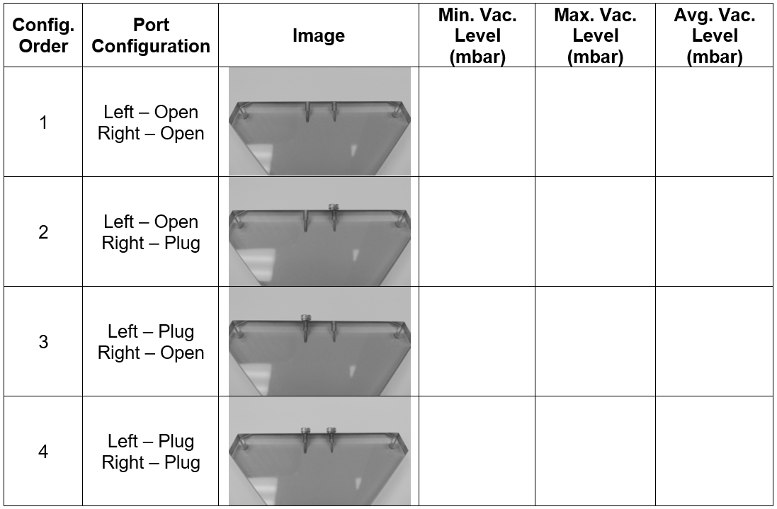
To achieve the desired vacuum level, start with the initial (both ports open) configuration and step through each configuration in order of increasing vacuum level until the maximum desired vacuum level is exceeded.
For example, if configuration 3 results in an average vacuum level above 237 mbar it is not necessary to test configuration 4.
|
|
Note— The vacuum system can remain on and running when transitioning from one configuration to the next. Wait time between each configuration is not required if the system remains running when the configuration is changed. |
The final configuration should be the one that best fits the optimum level as described above. Images of each configuration and the test order are provided in the datasheet below.
The vacuum level in the manifold rapidly fluctuates due to pulses created by the pumps and the dynamics of the system.
Therefore, the vacuum level reported in Service Software will vary each time the vacuum sensor is read.
The vacuum level of each configuration should be evaluated based on an estimated average value.
This can be accomplished by repeatedly reading the vacuum level about once per second for about 20 seconds.
While repeatedly reading the vacuum level, note the highest and lowest observed values.
Record the highest and lowest observed values in the table below for each configuration.
Average the highest and lowest observed values to get the estimated average value for each configuration. Select the configuration that best meets the criteria described above.
Verification
The optimum vacuum is between -203mbar and -270mbar and the vacuum pump speed must read above 1650rpm
Utilizing the Panther Main Assay![]() Procedures required to prepare and perform a specific test. In the context of this document, assay refers exclusively to a Hologic test, such as Aptima Combo or Ultrio. software, perform a system prime to verify that the vacuum system functions properly during Magwash
Procedures required to prepare and perform a specific test. In the context of this document, assay refers exclusively to a Hologic test, such as Aptima Combo or Ultrio. software, perform a system prime to verify that the vacuum system functions properly during Magwash![]() Magnetic washer aspirations.
Magnetic washer aspirations.
|
|
Note—The vacuum level is verified during the configuration procedure described above. |
 button at the top of the page to send feedback, comments, or change requests.