Parts and Materials Required
- Hex key, 2 mm
- Hex key, 3 mm
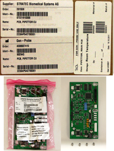
 PIPETTOR, MAIN PCB
Time Required
- 15 minutes
Removal Procedure
- Remove the gantry shield.
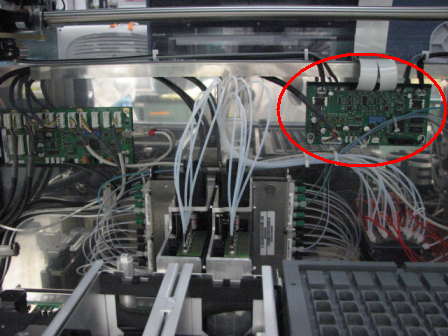
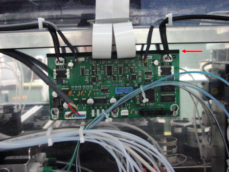
- Locate the Pipettor PCB inside the Panther System. The PCB is located to the back of the Sample Bay as shown in the following photo.
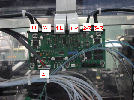
- Mark the cables as shown in the following photo.
- L = Left arm
- R = Right arm
- 1-L = X-Flex cable
- 2-L/R = X-encoder
- 3-L/R = X motor
- 4 = CAN bus
- Unplug the cables.
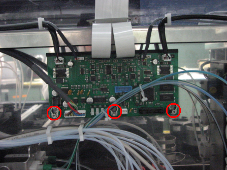
- Loosen the three 3 mm screws that secure the PCB.
- Remove the PCB by sliding the board down and out from the black plastic standoff.
Replacement Procedure
- Reverse the removal procedure.
- Verify that the PCB is seated in the black plastic standoff slot.
- Verify that the X-flex cables will not interfere with pipettors traveling in an X-direction.
- Install Panther System firmware.
Verification
|
|
Warning—Shut off the system immediately if Pipettors do not home in the correct direction or move to the incorrect Z-travel position. Perform system setup to install firmware. |
- Verify Pipettors initialize properly (Pipettors should move up in the Z-direction during homing).
 button at the top of the page to send feedback, comments, or change requests.