Parts and Materials Required
- Allen wrench, 2.5 mm
- Cable ties
-
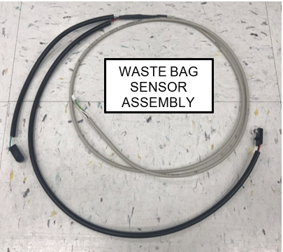
CONTINUOUS ACCESS WASTE BAG SENSORS
Time Required
- 30 minutes
Removal Procedure
- Put on proper PPE.
- Power down the Panther System.
- Open the left and right side panel doors.
- Open the Waste Drawer.
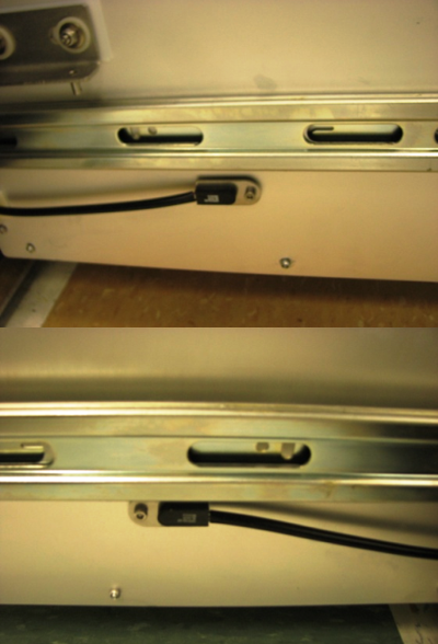
 Locate the waste present sensors on the left and right sides of the Waste Drawer..
- Using a 2.5 mm Allen wrench, remove the screw that secures each sensor in place (one on the left side and one on the right side of the drawer).
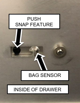
- Remove the two waste bag presence sensors from their mounting plates.
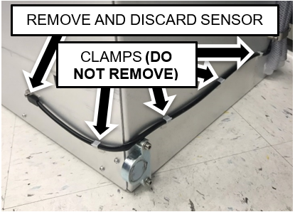
Push the snap features from the inside of the drawer using a small Allen key if necessary. - Unclip the cables from the harness clamps on the sides and back of the drawer.

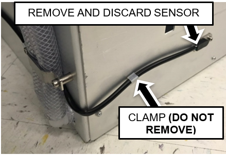
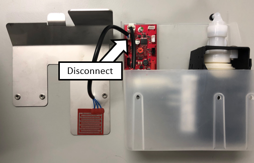
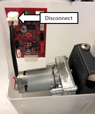
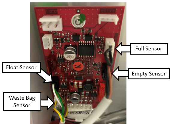
Note—Do not remove the cable clamps from the sides of the drawer. - Disconnect the waste bag and bottle sensors from the Transfer Pump PCB.
- Remove the Waste Drawer Bag sensor cable from the bottom of the waste drawer. Cut the cable ties if necessary.
Replacement Procedure
- Install the new Waste Bottle Sensor Cable.
The short branch routes to the left side of the drawer and the long branch is on the right side (as you face the system).
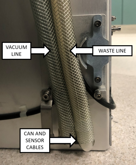
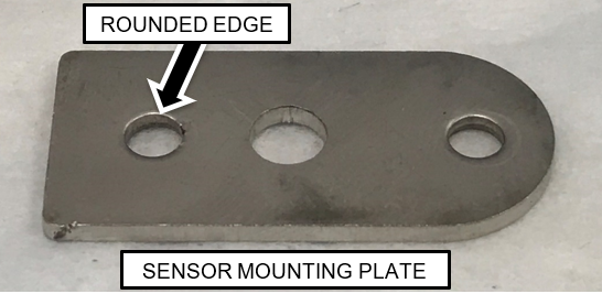
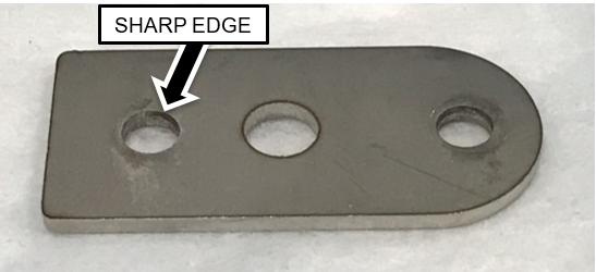
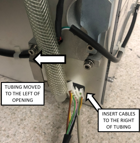
Note—The sensor modules have snap features that press into a hole in the sensor mounting plates. One side of the mounting plate will have a slightly more rounded edge than the other. The snap is pressed in from the side with the more rounded edge. - Route the branches of the cables behind the drawer and position the cable behind the vacuum tubing as shown.
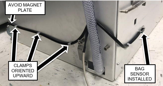
- Secure the cable to the sides of the drawer with the cable clamps oriented upward as shown above. Route the right-side of the branch such that it will not interfere with the magnet interface block as shown above.
- Route the Waste Bag Sensor Cables through the opening to the right of the vacuum tubing.
- Pull up the cable slack such that the main branch of the cable enters through the opening. This will ensure that the outer jacket protects the cable at the edge of the opening.
- Re-attach the metal tubing clamp.
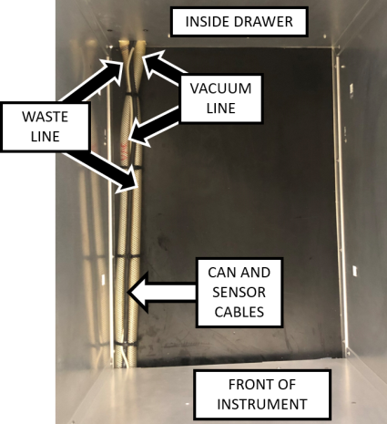
- Inside the Waste Drawer, crisscross the vacuum tubing over the waste tubing as shown in the image below.
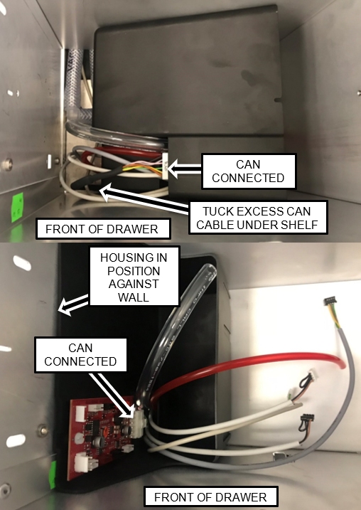
- Position the housing in the front left of the drawer and route the cables (and tubing) through the opening in the housing as shown.
- Re connect ALL Cables. Tuck the excess CAN cable under the shelf so the housing can be moved into position.
- Re connect ALL cables as shown.
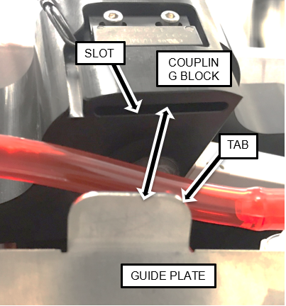
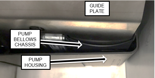
Note—Make neat service loops with the excess cable. - Position the Guide Plate in the Pump Housing as shown.
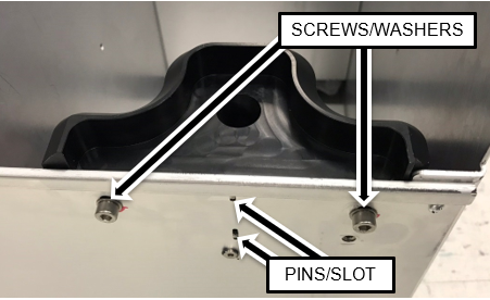
Note—The Guide Plate should be to the left side (inside) the metal chassis around the bellows of the Transfer Pump as shown. - Position the Coupling Block such that the Guide Plate tab is inserted into the slot on the underside of the Block and the Block Guide Pins are in the slots in the left side of the drawer.
Note—Tubing color will be clear. - Secure the Coupling Block in position using the screws and washers supplied in the kit
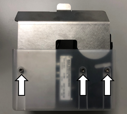
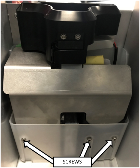
(or retained from the original block). - Secure the Guide Plate in the housing with the 3 screws removed in a previous step using a 4 mm Allen key.
- Reinstall the Waste Drawer Cover
- Close the left and right side panel doors.
- Close the Waste Drawer.
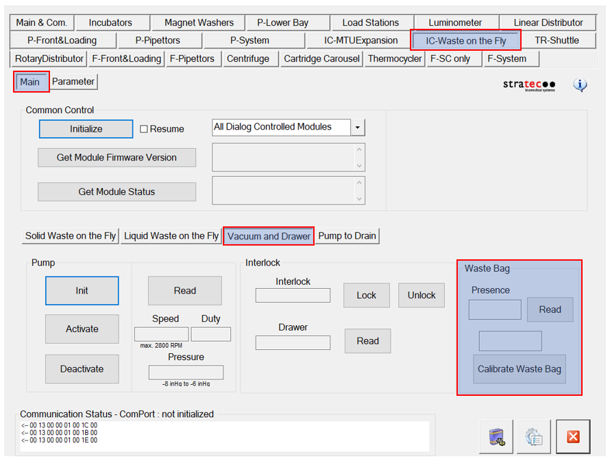
- Calibrate the Waste Drawer bag sensor.
 button at the top of the page to send feedback, comments, or change requests.