PCAP Monitor Upgrade
Purpose
This procedure provides instructions on how to upgrade an LED Panther Monitor to a 19" PCAP Monitor.
What is Affected
A new 19" PCAP (Projected Capacitive Touch) monitor upgrade is available for installation on Panther Systems, Serial # 02306 and below.
PCAP Monitors were cut in on Serial # 02307 and above.
Parts and Materials Required
- Panther Tool Kit
- PCAP Monitor Upgrade Kit
- PCAP Monitor
- Monitor Arm
- VGA Cable
- Monitor Power Cable
- USB Monitor Cable
- USB Hub Power Cable
- Canopy Frame Bracket and Bracket Cover
- USB Plate
- USB Hub
- (4) M4x8 Hex Screws (for the monitor)
- (2) M6x20 Hex Screws (for the Monitor Arm)
- (2) Cable Clips (to secure cables)
- Cable Spiral Wrap (20cm and 8cm) for cable dressing
- Proper PPE

|
Note—The 4 new cables that are included in this upgrade kit are longer than the existing cables. These longer cables will allow the PC to be pulled out of the PC Bay for maintenance. |
Time Required
- 3 Hours
Procedure
- Put on proper PPE.
- Shutdown the Panther System.
- Turn off the system main power switch. (Leave the PC on)
- Open and remove the Left Side Door to access the PC.
Note— If the system is a Fusion Refer to Unfuse and Fuse Fusion Procedure to separate the Fusion. - Verify the new monitor works before continuing with this procedure.
- Unpack the new PCAP Monitor and the new monitor cables.
- Disconnect the existing VGA, USB, and power cables from the back of the PC.
- Connect the new VGA and power cables to the PC and the PCAP Monitor.
- Verify the PCAP Monitor is functional.
Note—If the PCAP Monitor does not work, reconnect the old monitor and order another PCAP Monitor. - Disconnect the new cables from the PC and PCAP Monitor.
- Shutdown the PC.
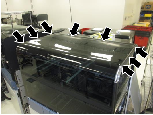
 Remove the Top Canopy by unscrewing the 8 screws on top of the canopy with a 2.5mm hex key.
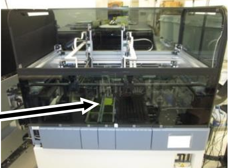
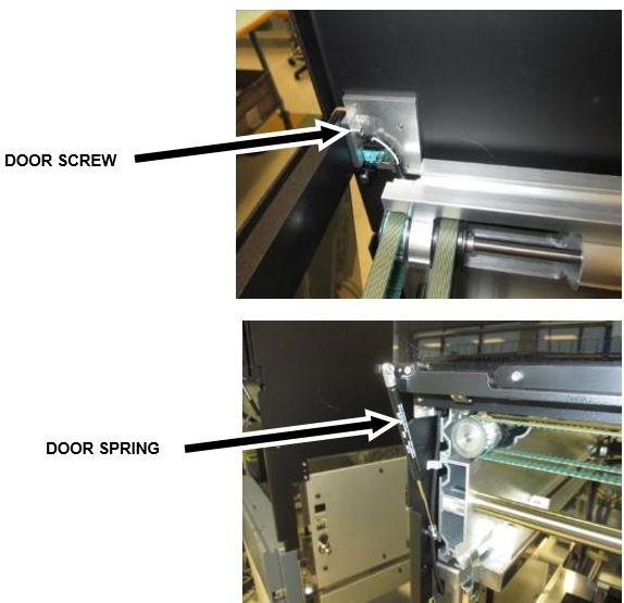
- Remove the Front Canopy Doors.
- Open both doors.
- Remove the door springs.
- Remove the 2 screws on the inside of the frame and set the doors aside.
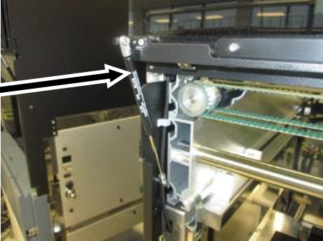
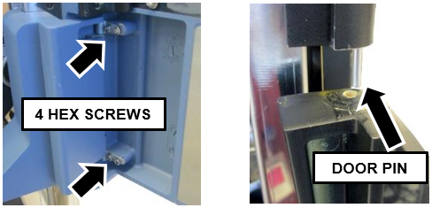
- Open the TCRTarget capture reagent—An assay-specific reagent added as part of specimen pipetting. Door and remove the 4, 2.5mm hex screws that hold the door on its hinges.
- Tilt and slide the TCR Door away from the Panther System to remove it from the door pin (the pin may look different than pictured below).
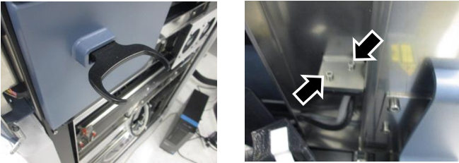
- Swing open (or remove) the Right-Side Door.
- Remove the hand-held scanner bracket by removing the two 2.5mm hex screws on the inside of the USB Hub.
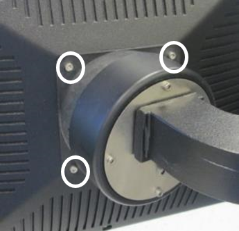
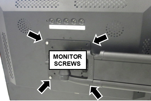
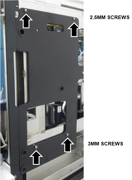
- Remove the four 3mm hex screws on the back of the monitor bracket.
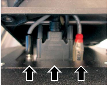
Note—Support the monitor while unscrewing the four screws. These four screws secure the monitor to the arm. - Remove the monitor from the monitor bracket by disconnecting the three cables from the back of the monitor.
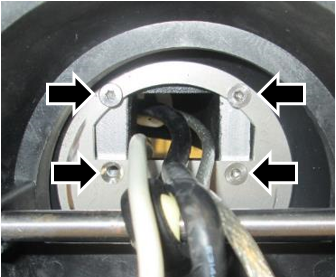
Note—It helps to free all the cables from the cable clips underneath the monitor arm. - Remove the four inner screws that secure the monitor gimbal to the arm with a 2.5mm hex key.
- Slowly pull the bracket away from the arm, allowing the 3 cables to pass through the center hole.
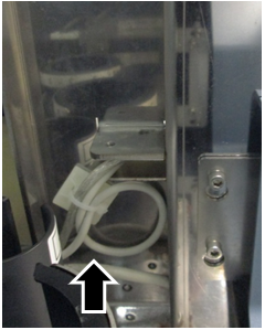
- Unclip the cables from any plastic clips underneath the monitor arm and let the three cables hang from the base of the USB Hub.
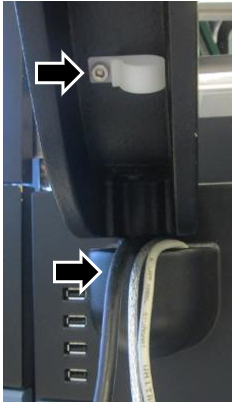
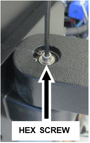
Note—Save the plastic cable clips and screws from the old monitor arm for cable dressing the new cables. - Take off the cap cover at the base of the monitor arm.
- Unscrew the 4mm hex screw.
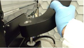
- Lift the monitor arm up and off the stanchion.
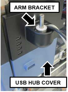
- Pull off the USB Hub Cover and let it hang loosely on the arm bracket. (The USB Hub Cover is a "press-fit" cover, no screws.)

Caution— DO NOT put any stress on the USB and power cable that connect to the USB Cover. - Disconnect the USB and power cable that connect the USB Hub.
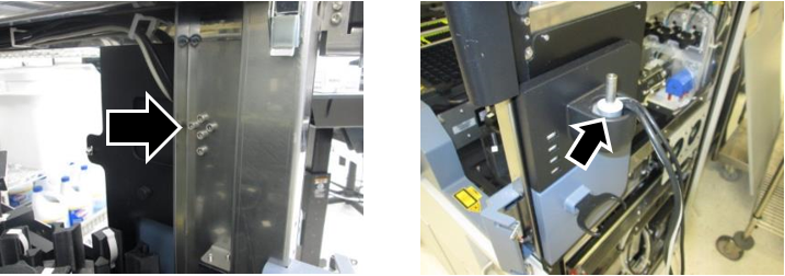
- Remove the five screws on the inside of the system to slide out and remove the old monitor arm gimbal.
- Pull the old monitor cables back through the USB Hub and Plate to the inside of the system.
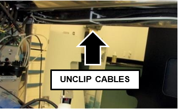
- Unclip the cables along the frame above the TCR Carousel all the way back to the corner, the cables will hang down out of the way by the top corner of the Pumps Module.
- Pull back the old USB Power cable as it will be replaced with a new cable.
Note—Pay attention to the exact route of the existing cables. Follow this route when routing new cables. - Remove the USB Hub.
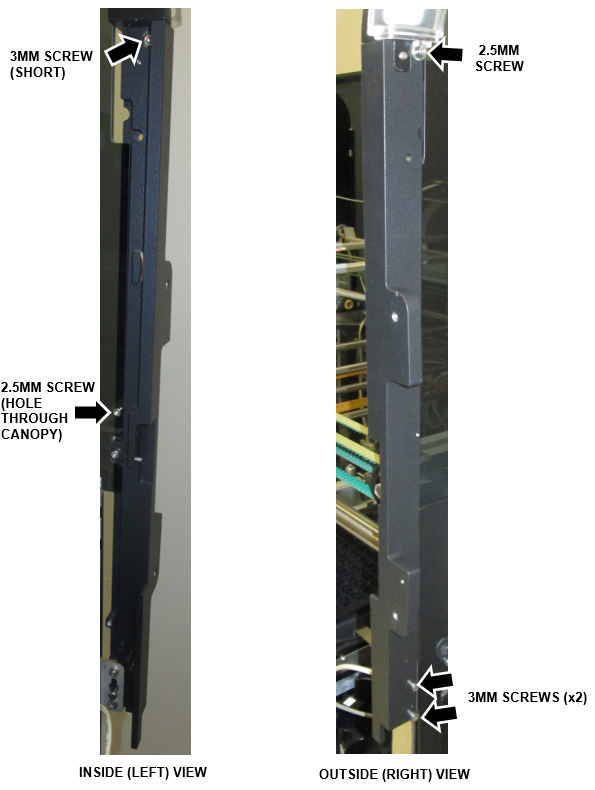
- Remove the old USB Plate (two 2.5mm hex screws and two 3mm hex screws) and discard.
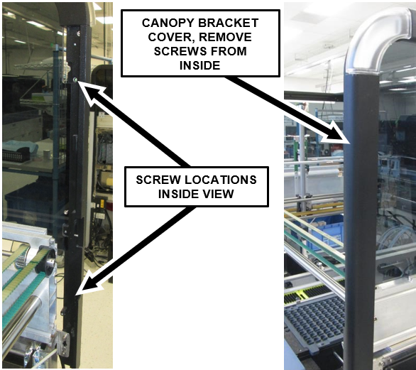
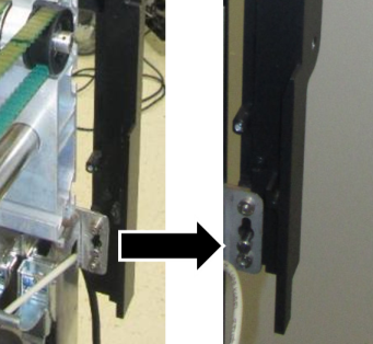
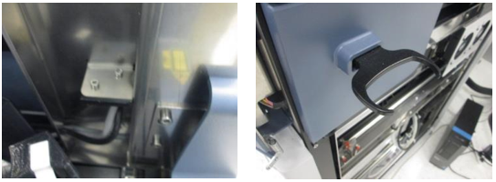
Note—SAVE THE SCREWS, these will be reused to install the new USB Plate. - Remove the two 3mm screws holding the right canopy bracket cover to the bracket. Access the screws from the inside of the bracket.
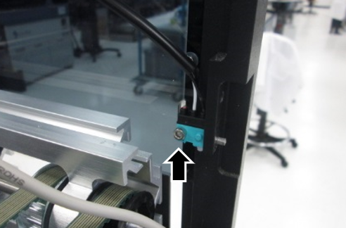
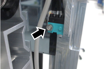
- Remove the 2.5mm hex screw that holds the canopy door sensor to the bracket.
Note—SAVE THE SCREW - Remove the LED PCB by removing the two 2.5mm screws that hold it to the frame.
Note—There are two small standoff bushings behind the LED that will fall out when the two screws are loosened. DO NOT let them fall into the system. - Disconnect the LED PCB and set aside (leave the canopy door sensor connected).
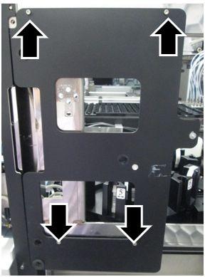
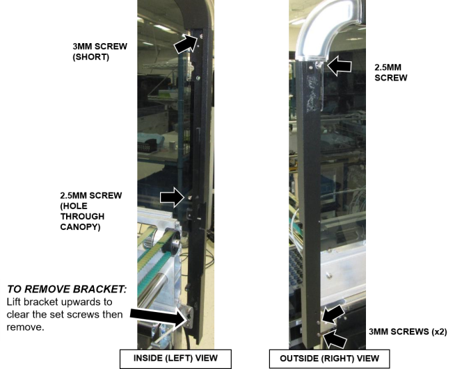
- Remove the old bracket. There are five screws that hold the bracket to the frame.
Note—SAVE THE SCREWS these screws will be used to install the new bracket. - Gently lift the bracket upwards to clear the set screws on the lower left of the bracket after the screws are removed.
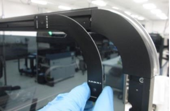
- Swap the canopy shock guide pin to the new bracket.
- Install the new bracket. Use the same five screws from the old bracket.
- Reconnect the LED PCB. Ensure the canopy door sensor cable is also securely connected.
- Install the LED PCB with the two 2.5mm screws and bushings.
Note—The two small standoff bushings are used behind the LED PCB. Don't let them fall into the system. - Reinstall the canopy door sensor using the 2.5mm screw.
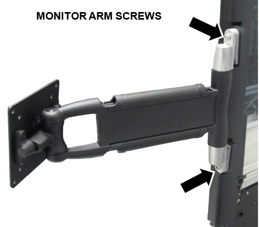
- Install the new monitor arm to the new bracket with two M6x20 socket head screw caps (5mm hex key).
Note—Ensure the plastic green arrow (on the inside of the plate) is pointing up. Remove the plastic arrow after install.
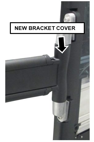
Note—If the plastic arrow is missing, there is a large spring that goes on the INSIDE of the arm. - Install the new bracket cover over the outside (right side) of the new bracket using two 3mm screws.
- Install the monitor to the monitor arm using eight M4x8 hex screws (3mm hex driver). Hold the monitor in place and get two screws started and tightened, then you can safely install the rest.
- The PCAP Monitor and Arm are now installed. The next steps will explain how to route the cables from the PC to the new PCAP monitor.
- Disconnect the Luminometer injector on top of the luminometer, located under the Pumps Module.
- Slide out the Mid-Bay Drawer all the way out.
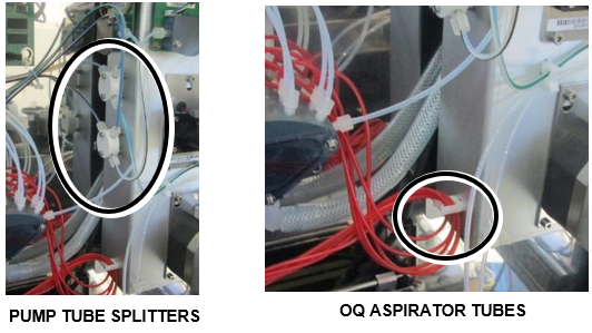
- If the Output Queue (OQ) aspirator tubes are affixed to the lower left side of the Pumps Module, unclip to allow slack in the tubes.
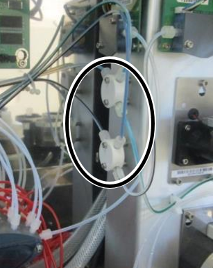
Note—Aspirator tubes may have different routing, just ensure tubes are clear of the pump. - Unscrew the two screws (2.5mm hex key) holding each white plastic splitter (Oil & Wash) on the left side of the Pumps Module to allow slack in the pump tubes.
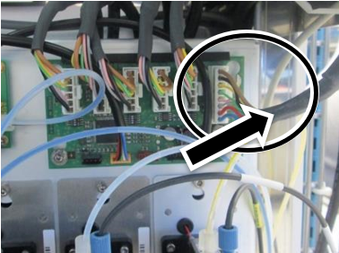
- Disconnect the CAN cable from the upper right front of the Pumps Module.
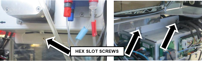
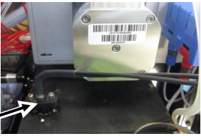
- Remove the hex slot screw underneath the Pump Module (3mm hex key), and loosen the two on top (3mm hex key) just enough to slide the Module up and off the posts.
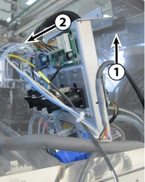
- Push the Mid-Bay Drawer back in until it is about 4-6 inches from the back. Slide the Pumps Module up an inch to clear the slots (1), then move it forward (2) and gently set it on the luminometer.
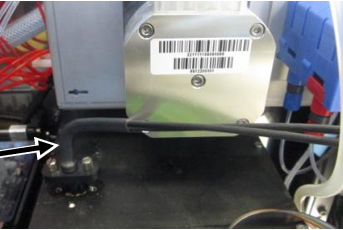
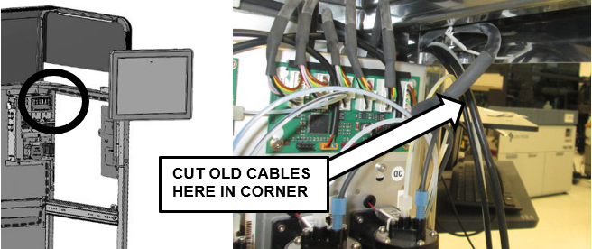
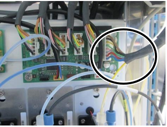
- Cut the four old cables in the back corner above the pump, and discard the loose ends.
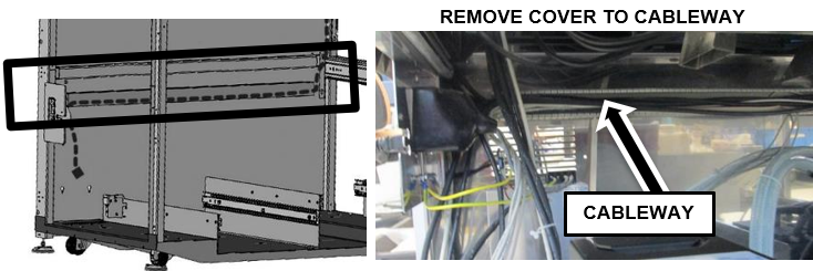
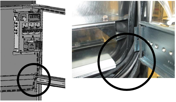
- Pull the Waste Drawer and UFD Drawer all the way out. Remove the plastic cover off cableway across the back to expose the cables.
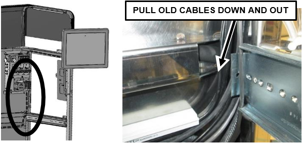
- Pull the other sections of old cable down and out of the vertical channel next to the Pumps Module and behind the UFD Drawer.
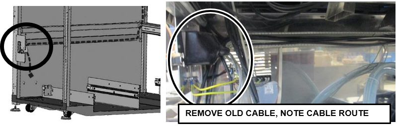
- Remove the old cables from the cableway across the back, disconnect the cable from the back of the PC and discard.
Note—Open existing cable clips as necessary and note the exact cable route that the old cables follow, especially in the back corners. Use the same route later when installing the new cables. - Install the new USB Plate (reuse screws from the old Plate).
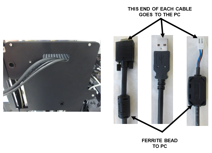
- Route the three new monitor cables from the inside of the frame, out through the hole in the USB Plate.
Caution—Ensure the correct end of each cable is routed through the hole for connection to the monitor. (The PC end of the VGA and power cables have a black component (ferrite bead) on the end of the cable. Do not route this end through the USB Plate.
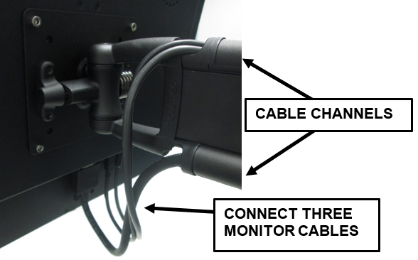
Note—Leave approximately 35'' of each of the cables outside the mounting plate. - Plug in all three new cables to the monitor and route the cables through the channels on the monitor arm. Run the VGA cable through the bottom channel, and the other two cables through the top channel. Snap the channel covers back into place.
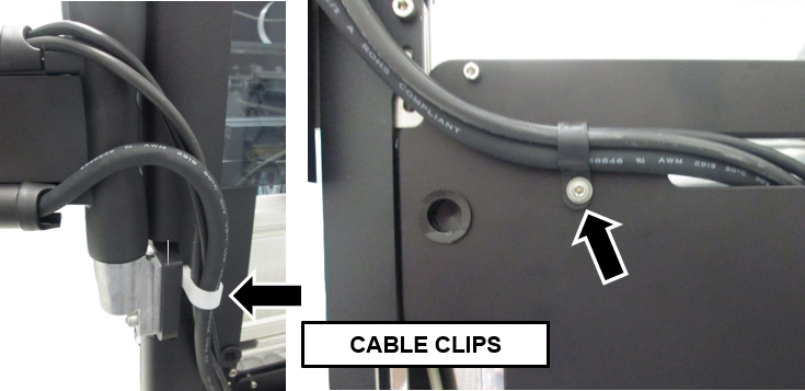
Caution—When routing the cables through the cable channels in the arm, keep slack in the cables to minimum but do not put too much stress on the cables at any point. The monitor arm must be able to swing all the way from one side to the other without any strain on the cables. - Attach cable clips on the back of the bracket and on the USB Plate shown below.
- Inside the chassis, route the new USB Power Cable as the old cable was run.
- Connect the two USB cables into the new USB Hub and reinstall on the USB Plate.
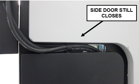
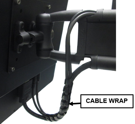
Note—Ensure the side door can still open and close. Re-adjust the cable routing through the cable clips as necessary. - Dress the cables under the monitor using the short cable wrap. Ensure there is not too much tension on the cables through the full movement of the arm.
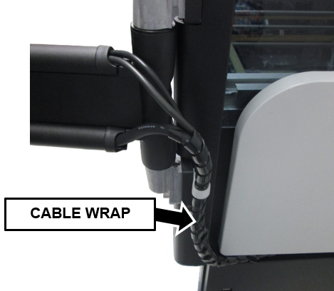
- Dress the cables down and through the USB Plate using the long cable wrap.
- Take off the cable clamps to wrap the cables together, the re-install the clamps around the dressed cables.
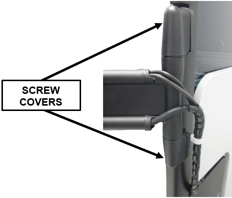
- Snap on the new monitor arm plastic covers that hide the screws.

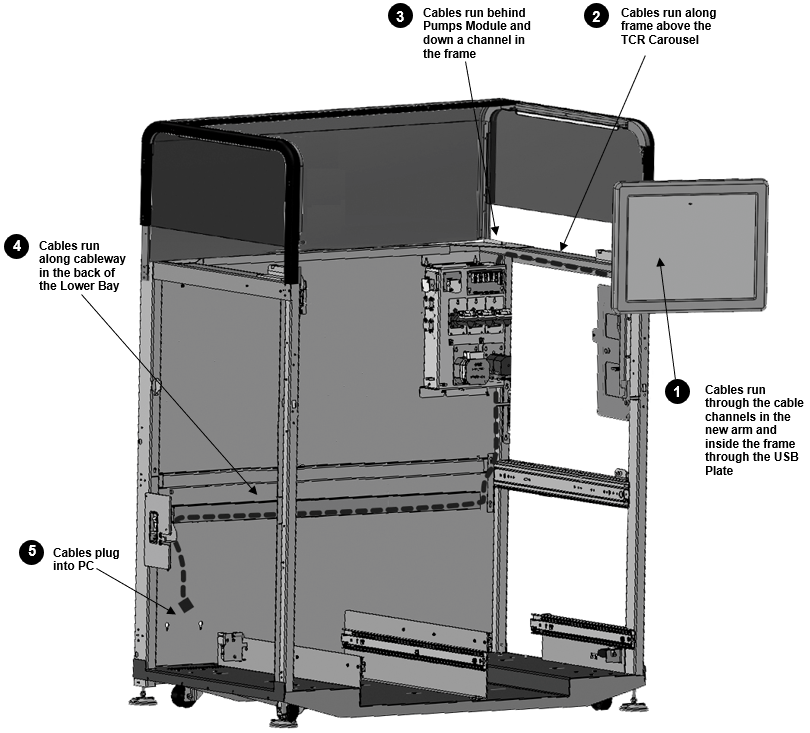
Cable Routing
|
|
Caution—The cable routing path shown above must be followed. The energized VGA cable may induce unwanted electromagnetic interference in PCB's or other electronics. The existing cable path is the only validated, approved, and EMI tested path. |
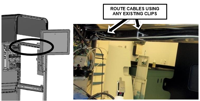
- Route the new cables from behind the USB Plate back to the corner above the Pumps Module. Follow the upper edge of the frame above the TCR Carousel, and reuse the existing clips to secure the monitor cables. Route the new USB Power cable in the same manner as the old one.
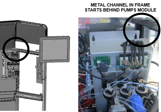
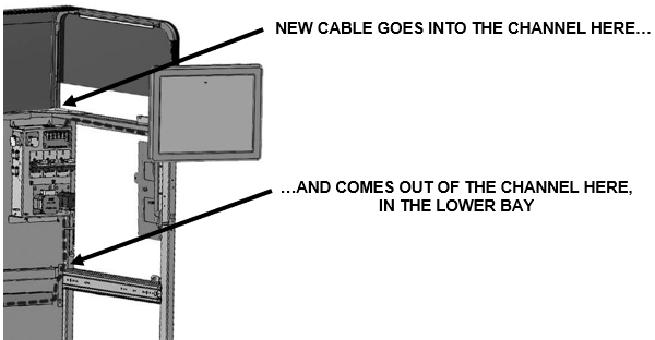
- Route the new cables behind the Pumps Module and into the channel in the frame. Follow the same path as the old cables.
- Route the new cables down the channel and into the Lower Bay. The cables should come out of the channel in the frame behind the UFD Drawer, below the Pumps Module.
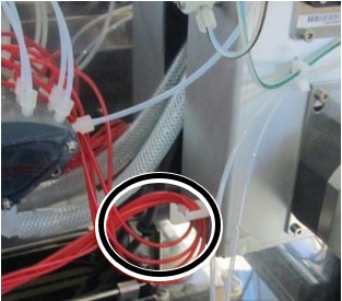
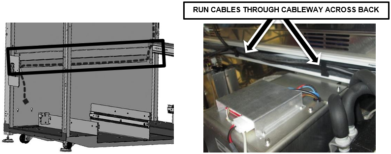
- Pass all the ends of the new cables over the Computer Bay. Gather the new and existing cables and place them into the beginning of the cableway behind the UFD Drawer as shown below.
Caution—When you route the cables in the back corner, ensure none of the cables or insulated water hoses will be pinched or in the way when the Mid-Bay Drawer is closed. Slowly close the drawer and visually verify the drawer can close and lock. - Run the new cables across the back to the Computer Bay and tuck all the cables into the cableway.
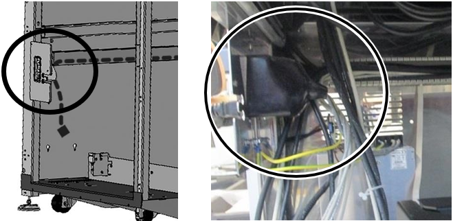
- At the back of the Computer Bay, route the new cables coming out of the cableway in the same way as the other existing cables. They should run behind the power supply plug. Unclip and re-clip existing clips as needed.
Caution—When you route the new and existing cables out of the cableway, ensure none of the cables will be pinched or in the way when the Mid-Bay Drawer is closed. Slowly close the drawer and verify the drawer can close and lock. - Connect the new cables to the PC, turn it on and verify the monitor is working.
- Finalize the cable routing across the back of the Lower Bay (ensure all cables are in place and connected, all clips are re-attached) and re-install the plastic cover over the cableway.
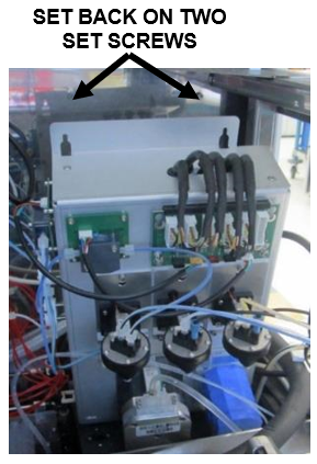
Note—Check the new and existing cables in the cableway again behind the UFD and in the PC Bay. Ensure none of the cables or insulated water hoses will be pinched or in the way when the Mid-Bay Drawer is closed. Slowly close the drawer and verify the drawer can close and lock. - Carefully lift and set the Pumps Module back onto the two set screws and tighten with a 3mm hex key.
Note—Ensure the Pump Module CAN cable is still run through the metal channel in the frame, or up and over the top of the Pumps Module from the rear corner so it doesn't get pinched or damaged when the Pumps Module is re-installed. - Re-install the third screw underneath the module. Slide out the Mid-Bay Drawer for easier access to the screw location.
- Re-attach the two Pump Tube Splitters on the left side of the Pumps Module with the (2.5mm) screws removed previously. Re-secure the OQ aspirator tubes in the clips (if present)..
- Plug the CAN cable back into the Pumps Module.
- Re-connect the Luminometer Injector on top of the Luminometer, under the Pumps Module.
- Close and lock the Mid-Bay Drawer.
Note—Use caution when closing the Mid-Bay Drawer, and ensure that none of the cables or insulated water hoses will be pinched or in the way when the drawer is closed. - Reattach the hand-held scanner bracket (2 screws, 2.5mm hex key).
- Re-install the TCR Door using the four 2.5mm hex screws that hold the door on its hinges. Tilt and slide the TCR door upwards to re-engage the pin.
- Re-install the Front Canopy Doors using two screws on the inside of the frame, and reattach the door springs.
Note—Use the Shock Compression Tool from the Panther Tool Kit to install the springs. - Re-install the Top Canopy using the eight screws on top of the canopy (2.5mm hex key).
Note—If the system is a Fusion, refer Unfuse and Fuse Fusion Procedure to separate the Fusion. - Power on the system and start the PC.
Monitor Configuration
- Change the monitor screen resolution to 1280 x 1024 (if it doesn't change automatically).
Note—If the Panther Image is 5.8.2 or above, Steps 2-22 are NOT required. - Login to the FSE Shield.
- Click the Command Prompt button.
- Type in services.msc.
- Press Enter.
- Right click the "Tablet PC Input Service" from the list of Services.
- Select Properties.
- From the "Tablet PC Input Service Properties" window, use the "Startup Type" dropdown menu to set the Startup Type to Automatic.
- Select the Apply button.
- Select OK.
- Restart the PC.
- Login to the FSE Shield.
- Click the Command Prompt button.
- Type in control.
- Press Enter.
- Select "Programs and Features" from the Control Panel window.
- Select "Turn Windows features on or off".
- When the Features list populates, scroll down to "Tablet PC Optional Components" and check the box to enable this feature. (If already checked, DO NOT uncheck. Leave the feature checked and proceed.)
- Select OK.
- Wait for the "Tablet PC Optional Components" feature to be configured. (This process can take up to 10 minutes if previously unchecked.)
- Restart the PC.
- Login to the FSE Shield.
- Click the Command Prompt button.
- Type tabletPC.cpl.
- Press Enter.
- From the "Pen and Input Devices" window, select the Touch tab.
- Uncheck the "Show the pointer when I'm interacting with items on the screen" checkbox.
- Select OK.
- Restart the PC.
Verification / Service Call Completion
- After reboot, verify the display and touchscreen functionality works correctly.
 button at the top of the page to send feedback, comments, or change requests.