Left and Right Chassis Fan Removal and Replacement
Purpose
Provides instructions to:
- Remove Left and Right Chassis Fans from Panther Systems below Serial # 00281.
- Install Left and Right Dual Chassis Fan Assemblies, which were cut-in on Panther Systems above Serial # 00280.
Parts and Materials Required
- Proper PPE
- Diagonal cutters (small)
- 8 Inch cable-ties (as needed)
- 4 mm Allen wrench
- Nitrile gloves
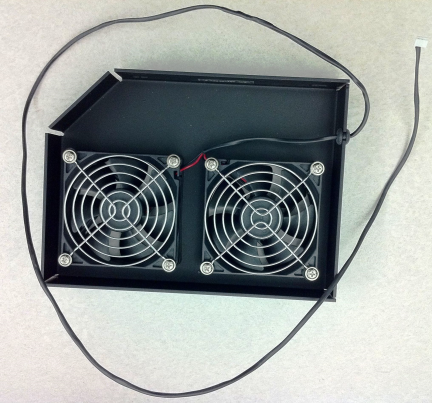
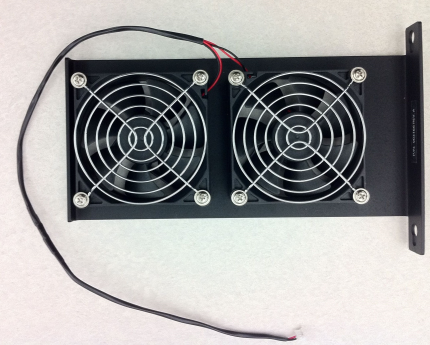
 Dual chassis fan, left
- Dual chassis fan, right
Preparation
- Put on proper PPE.
- Prepare the system for service.
- Power down the Panther System.
- Open both side panels of the system.
- Pull open the Service drawer and leave it fully extened for the entire procedure.
- Read the rest of this procedure before starting it.
Procedure
Removing and Replacing the Right Chassis Fan Assembly
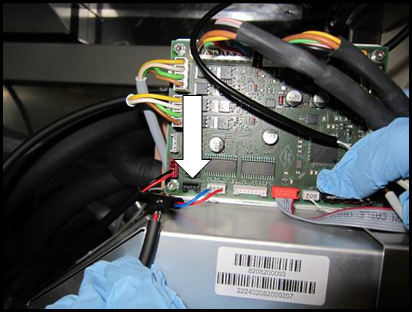
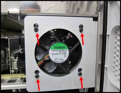
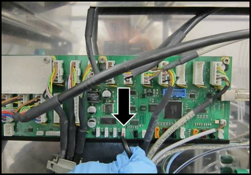
- Unplug the 4-pin fan connector from the PCB (shown unplugged).
- Pull the fan cable through the chassis of the system.
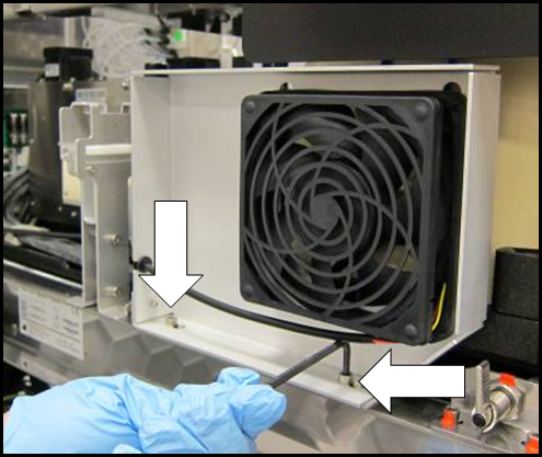
- Remove the chassis fan from the bracket by sliding the rubber mounts up.
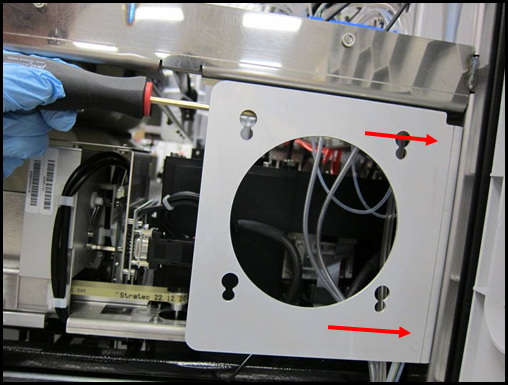
- Using a 4 mm Allen wrench, loosen but do not remove the 2 M6 bracket mount screws on the back side of the bracket. (Screw location approximated by red arrows.)
- Slide the bracket up to remove it from the system.
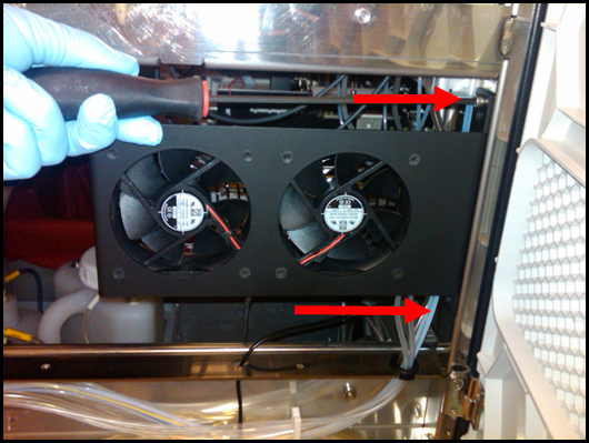
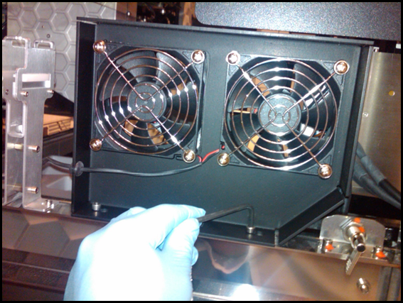
- Using a 4 mm Allen wrench and the same mounting screws from the original bracket, install the new dual right chassis fan assembly [P/N 902976].

NOTE—Make sure the bracket is pushed all the way down before tightening the mounting screws. - Route the fan cable through the cable routing openings in the chassis.
- Replace all removed zip-ties in the same fashion as the original fan assembly.
- Plug the 4-pin connector into the circuit board.
- Test the Waste Drawer opening & closing for cable snags & obstructions. Adjust as needed.
- Close the right side door panel.
Removing and Replacing the Left Chassis Fan Assembly
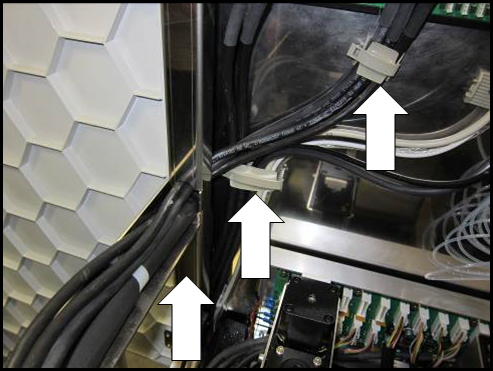
- Unplug the 3-pin fan connector from the COP circuit-board.
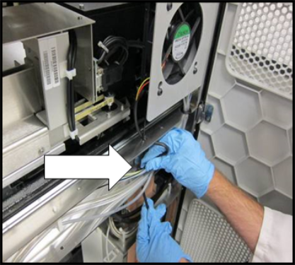
- Unclip the wire-clips identified and feed the fan cable through the chassis of the system.
NOTE—Make sure to remove any cable-ties holding the fan cables prior to pulling the fan cable. - Using a 4 mm Allen wrench, loosen, but not remove, the 2 M6 bracket screws and slide the bracket towards the back of the system to remove it from the system.
- Using the same mounting screws used with the original bracket, install the new dual left chassis fan assembly [P/N 903165].
- Route the fan cables through the cable routing openings in the chassis and cable-clips.
- Replace all removed cable-ties in the same fashion as the original fan assembly.
- Plug the 3-pin connector into the COP circuit board.
- Test the Service Drawer opening & closing for cable snags & obstructions, adjust as needed.
- Close the left side door panel.
- Proceed to Verification.
Verification
- Initialize the system by using one of the following methods:
- Method 1:
- Launch Panther Software and allow the system to initialize.
- Select Shutdown when in setup status
- Method 2:
- Launch Service Software and
- Initialize by inputting the following hex command into the Service Software command terminal:
02 48 00 00 1E 00 10 02 02 1D 00 10 00 00 00 80 00 00 00 00 B0 04 00 00 00 00 00 00 00 00 00 - Verify that the dual chassis fan, right, is properly connected by turning the fan ON and OFF by inputting the following hex commands in the Panther Service Software command terminal:
- Turn Dual Chassis Fan, Right, ON:
18 08 00 00 0E 01 - Turn Dual Chassis Fan, Right, OFF:
18 08 00 00 0E 00 - Verify that the dual chassis fan, left, is properly connected by turning the fan ON and OFF by inputting the following hex commands in the Panther Service Software command terminal:
- Dual Chassis Fan, Left, ON:
04 08 00 01 00 01 - Dual Chassis Fan, Left, OFF:
04 08 00 01 00 00 - Verification is complete.
 button at the top of the page to send feedback, comments, or change requests.