Linear Distributor General Information
Description
The Distributor is designed to transport MTUs to the different modules. It contains the following axes:
- Hook axis
- Theta-axis
- X-axis
- Z-axis
Interfacing Modules
The Distributor interfaces with every module located on the Service Drawer, including:
- Chiller Ramp
- High Temp (HT), Transition, and Amplification (AMP) Incubators
- Load stations
- Luminometer
- Magnetic Parking stations
- Magnetic Wash stations
- MTU
 Multi-tube unit—Container used to process tests in the instrument. An MTU contains five separate reaction tubes. The MTU is moved through the instrument by the linear distributor and includes five tiplets for pipettiing to be used in the mag wash station. Input Queue
 - Output Queue
- Sample Mix Station
Theory/Sequence of Operation
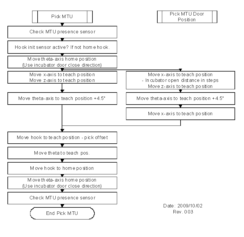
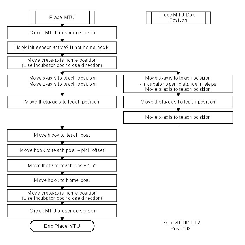
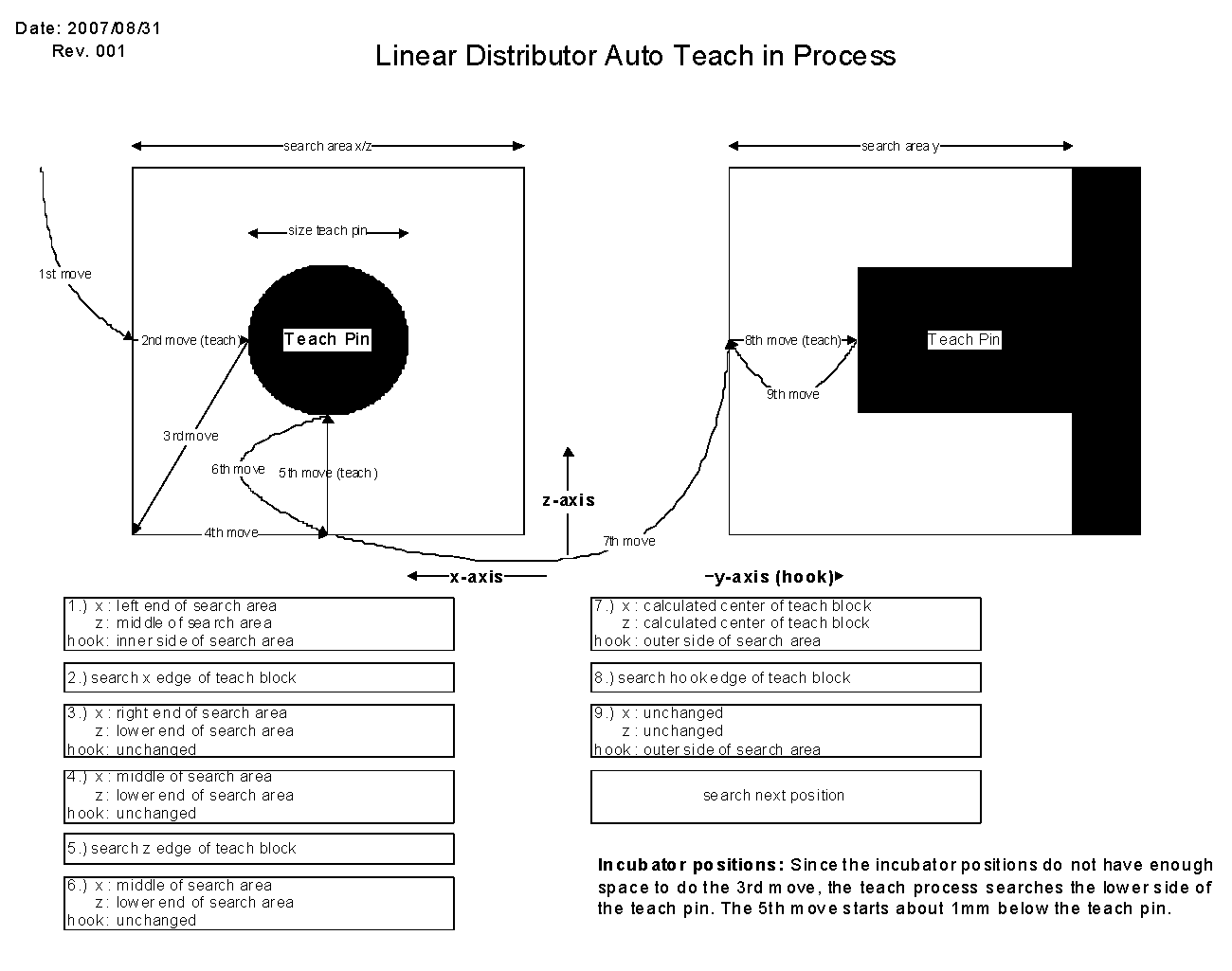
The Distributor transfers MTUs to the various modules in the Panther system. Its transfer mechanism is based on a hook and rail system that pushes and pulls the MTU between the support rails of the other modules. For all modules, the Distributor rotates a few degrees from normal, extends the hook, rotates back to normal, then retracts the hook in order to pick an MTU. The X-axis runs the length of the system. The Theta-axis rotates 270° to access all sides of the deck. The distribute-axis moves a hook to distribute MTUs. A flag-activated optical sensor detects the presence of an MTU. The Z-axis compensates the overall system tolerances and allows teaching in the field. An additional module calibration sensor allows for automatic calibration to the system modules.
Flow Diagrams
Click on a heading to open a diagram. Click a second time to close the diagram.
Distributor Failure Positions
The following table identifies failure positions for the Distributor.
- Position—The index position of the Distributor location.
- Module—The module at which the Distributor is located.
| Position (dec) |
Position (hex) |
Module |
|---|---|---|
| 00 | 00 | MTU Input Queue |
| 01 | 01 | AMP Load Station |
| 02 | 02 | HPA |
| 03 | 03 | Incubator #1—High Temperature |
| 04 | 04 | Incubator #2—Transition |
| 05 | 05 | Incubator #3—AMP |
| 06 | 06 | Magnetic Wash Station 1 |
| 07 | 07 | Magnetic Wash Station 2 |
| 12 | 0C | Sample Mix Station |
| 13 | 0D | Luminometer |
| 14 | 0E | Output Queue |
| 15 | 0F | Service Queue |
| 16 | 10 | Magnetic Parking (left) |
| 17 | 11 | Magnetic Parking (right) |
| 18 | 12 | Chiller Ramp, Slot 1 (left) |
| 19 | 13 | Chiller Ramp, Slot 2 |
| 20 | 14 | Chiller Ramp, Slot 3 |
| 21 | 15 | Chiller Ramp, Slot 4 |
| 22 | 16 | Chiller Ramp, Slot 5 |
| 23 | 17 | Chiller Ramp, Slot 6 (right) |
| 24 | 18 | Read MTU Barcode Position |
| 25 | 19 | Sample Dispense Slot |
| Fusion Handoff Location |
 button at the top of the page to send feedback, comments, or change requests.