Communication and Organization Processor (COP) General Information
Theory/Sequence of Operation
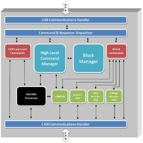
The communication and organization processor (COP) communicates with the PC via a USB serial interface. The COP communicates via a CAN interface with the subassemblies, as shown in the following diagram.
COP Modes
Hello/Connect Mode
After power up, a time delay will give the possibility to initialize for the subassemblies connected via CAN-BUS. According to a fixed list of members which must be available, COP checks for the connection of all processors/subassemblies.
Download Mode
The COP firmware and each module connected to the CAN BUS can be updated in this operation mode. The COP is set to this operation mode by connecting a download adapter to the serial port. After a power up, the COP is able to download all firmware modules using the system download tool.
Normal Operating Mode
In normal operating mode, this module supports the command interface. Initiated by appropriate commands from the normal operation mode, the COP can enter sub-modes that exclude each other.
- Initialization of the system with:
- Receipt and transfer of all parameters to the respective subassembly drivers
- Control of the process of mechanical initialization
- Priming of all subassemblies which work with liquids
- Cleaning reaction MTUs from the system as a maintenance task.
Standby Mode
Entering the standby mode, the COP sends standby commands to all subassemblies and then enters its own standby state. Only a RESUME command leaves the standby state.
Service Mode
In the service mode, the COP hands control over to the CM, thus enabling service functions, including:
- Teaching the machine-related parameters
- Trigging all subassemblies separately
- Adjusting global parameters
A de-initialization command leaves the service mode.
Module Temperature Data
The COP polls the modules for temperature information. The low-level responses from the modules queue for transmission to the PC.
The following modules are polled:
- Amp Load Station
- HPA
 Hybridization protection assay—The Hologic HPA technique uses a specific DNA probe, labeled with an acridinium ester detector molecule that emits a chemiluminescent signal. Load Station
 - Vacuum/Cooling Module
- Reagent Bay
- Sample Bay
- Incubators
- Chiller
Luminometer Process Control Data
The COP collects the process control data from the Luminometer and buffers it for transmission to the PC when communication is idle.
Output Queue process Control Data
The COP collects the process control data from the Output Queue and buffers it for transmission to the PC when communication is idle.
Pump Monitor Process Control Data
The COP collects the process control data from the Pump Monitor module and buffers it for transmission to the PC when communication is idle.
Pump Monitor Vacuum Pressure
The COP sends the vacuum pressure measurement made by the Pump Monitor module each time a response is received by the background task that transfers the vacuum pressure to the Vacuum/Cooling Module.
 button at the top of the page to send feedback, comments, or change requests.